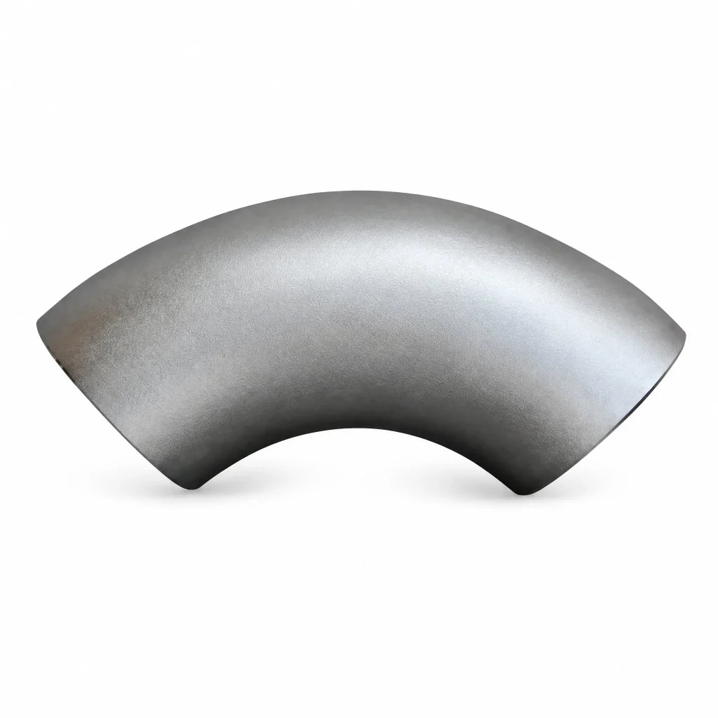
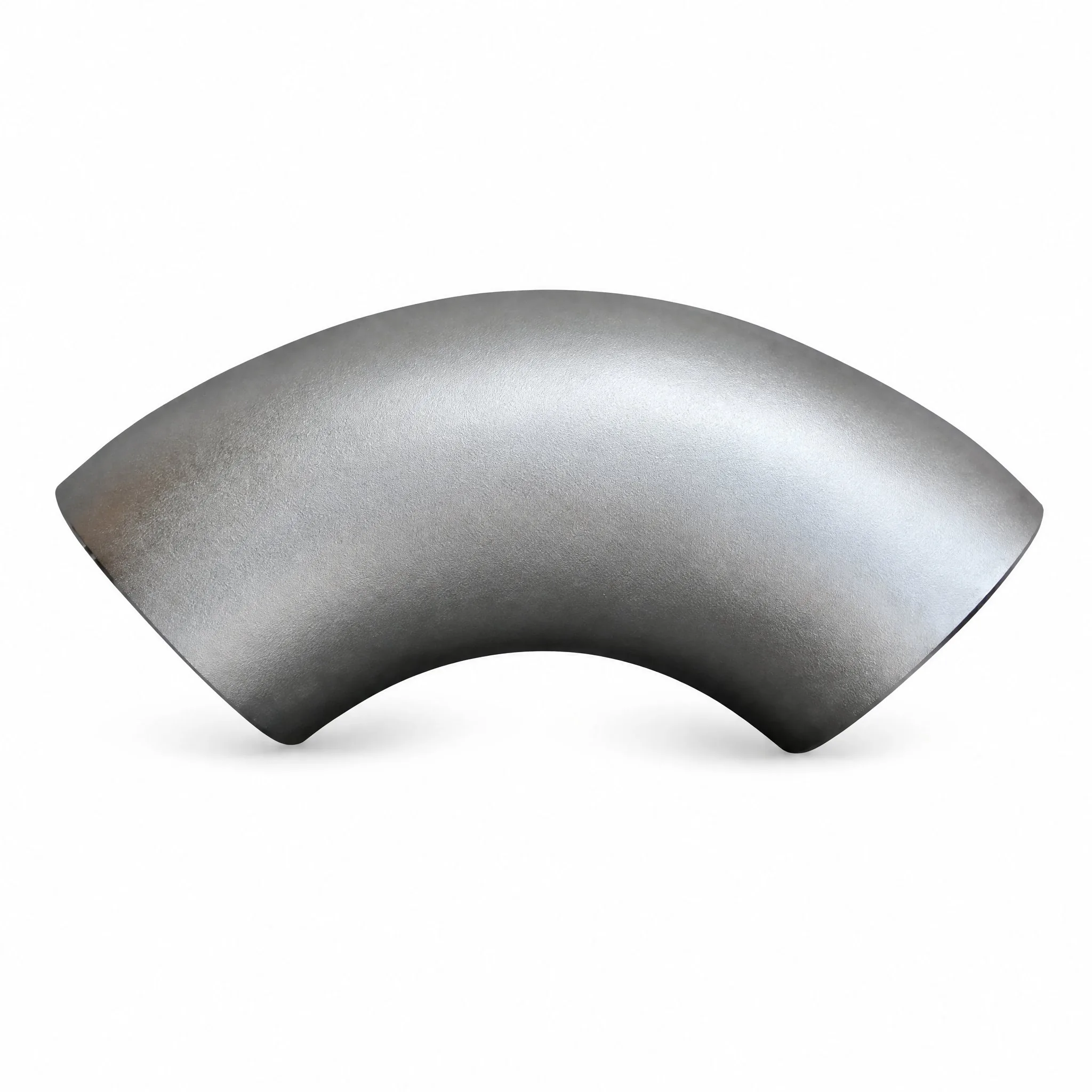
90° Long Radius Elbow
Product Description
The most common fitting for changing flow direction by 90 degrees. Long Radius (1.5D) design minimizes pressure drop and provides smooth flow transition.
Manufactured by cold forming or hot forging, followed by heat treatment where required, per ASME B16.9 dimensional tolerances. Available in Schedule 10 through XXS wall thicknesses.
Applications
The 90-degree long radius elbow (1.5D centerline radius) is the most widely used fitting for changing flow direction in industrial piping. Its generous bend radius minimizes turbulence and pressure drop, making it standard in oil and gas gathering lines, refinery process piping, power plant steam loops, and chemical plant transfer lines handling media at temperatures from -29°C to 425°C with WPB carbon steel.
Typical installations include pump discharge risers, tank nozzle turns, compressor station piping, and pipeline pig launcher transitions. In slurry and abrasive service, the long radius design reduces erosion compared to short radius elbows, extending fitting life in mining tailings and cement powder transport systems.
Stainless WP304/WP316 elbows serve food and beverage processing, pharmaceutical CIP return lines, and seawater cooling systems. Low-temperature WPL6 grades are specified for LNG transfer and refrigeration ammonia piping down to -46°C. Sizes from NPS 1/2″ to 48″ cover everything from instrument headers to cross-country transmission lines.
Quality Assurance & Certification
Each 90° LR elbow is manufactured to ASME B16.9 dimensional tolerances, formed by hot induction bending or cold mandrel pushing, and heat-treated per material specification. We supply EN 10204 3.1 mill test certificates with heat chemistry, tensile/yield, and Charpy impact data. Heat number stamping on the bevel end ensures full traceability.
NDT options include radiography (RT) for weld seam inspection on welded elbows, ultrasonic thickness (UT) verification at the extrados, and liquid penetrant (PT) on stainless surfaces. Hydroscopic dimensional checks confirm centerline radius, wall thinning, and end bevel angles. Third-party inspection by BV, SGS, or TUV is available for critical pipeline projects.
Butt-weld ends are protected with plastic bevel covers, carbon steel elbows receive anti-rust paint or oil, and all elbows are packed in wooden crates or strapped to pallets for ocean freight. Each piece is labeled with size, schedule, material grade, heat number, and ASME B16.9 compliance marking.
ASME Standard Data
This fitting is manufactured to ASME B16.9-2018, Factory-Made Wrought Buttwelding Fittings. This Standard covers overall dimensions, tolerances, ratings, testing, and markings for factory-made wrought buttwelding fittings in sizes NPS 1/2 through NPS 48 (DN 15 through DN 1200).
1. Scope and Size Range
This Standard covers overall dimensions, tolerances, ratings, testing, and markings for factory-made wrought buttwelding fittings in sizes NPS 1/2 through NPS 48 (DN 15 through DN 1200).
2. Units Policy — SI and U.S. Customary Must Not Be Mixed
This Standard states values in both SI (Metric) and U.S. Customary units. These systems of units are to be regarded separately as standard. Within the text and tables, the U.S. Customary units are shown in parentheses. The values stated in each system are not exact equivalents; therefore, it is required that each system of units be used independently of the other. Combining values from the two systems constitutes nonconformance with the Standard.
3. NPS–DN Relationship
DN/NPS: 15=1/2, 20=3/4, 25=1, 32=1-1/4, 40=1-1/2, 50=2, 65=2-1/2, 80=3, 100=4. NOTE: For NPS > 4, DN = 25 × NPS.
4. Materials — ASME B16.9 Table 5-1 Material Groupings
Wrought fittings covered by this Standard shall be in accordance with ASTM A234, A403, A420, A815, B361, B363, B366, or the corresponding specification in ASME BPVC Section II. The term “wrought” denotes fittings made of pipe, tubing, plate, or forgings.
| Group No. | Material | ASTM / ASME Specification |
|---|---|---|
| Group 1 | Carbon and low-alloy steels | ASTM A234/A234M, ASTM A420/A420M |
| Group 2 | Austenitic and duplex stainless steels | ASTM A403/A403M, ASTM A815/A815M |
| Group 3 | Nickel alloys | ASTM B366/B366M |
| Group 4 | Aluminum alloys | ASTM B361 |
| Group 5 | Titanium alloys | ASTM B363 |
Source: ASME B16.9-2018, Table 5-1 Material Groupings (corpus lines 674-676; OCR-recovered mapping, verified against standard group order).
5. Marking and WP / Special-Fitting Certification
Each fitting shall be permanently marked to show: (a) manufacturer’s name or trademark; (b) material identification, either the ASTM or ASME grade designation; (c) schedule number or nominal wall thickness in mm; (d) size — the NPS identification number related to the end connections; (e) compliance — see para. 4.4. A manufacturer may supplement these mandatory markings with others, including a DN size designation, but confusion shall be avoided.
Standard fittings: certified by prefix “WP”. Special fittings: certified by supplementary suffix: “S58” of ASTM A960 applies for A234, A403, A420; “S8” for A815; “SPLD” for B361, B363, B366.
6. Dimensional Tables — Long Radius Elbows (ASME B16.9-2024 Table 6.1-1)
Center-to-end dimensions A (90°) and B (45°) for long radius elbows, NPS 1/2–48.
| NPS | Outside Diameter at Bevel | 90° Elbow A | 45° Elbow B |
|---|---|---|---|
| 1/2 | 21.30 mm (0.84 in.) | 38 mm (1.50 in.) | 16 mm (0.62 in.) |
| 3/4 | 26.70 mm (1.05 in.) | 38 mm (1.50 in.) | 19 mm (0.75 in.) |
| 1 | 33.40 mm (1.32 in.) | 38 mm (1.50 in.) | 22 mm (0.88 in.) |
| 1-1/4 | 42.20 mm (1.66 in.) | 48 mm (1.88 in.) | 25 mm (1 in.) |
| 1-1/2 | 48.30 mm (1.90 in.) | 57 mm (2.25 in.) | 29 mm (1.12 in.) |
| 2 | 60.30 mm (2.38 in.) | 76 mm (3 in.) | 35 mm (1.38 in.) |
| 2-1/2 | 73 mm (2.88 in.) | 95 mm (3.75 in.) | 44 mm (1.75 in.) |
| 3 | 88.90 mm (3.50 in.) | 114 mm (4.50 in.) | 51 mm (2 in.) |
| 3-1/2 | 101.60 mm (4 in.) | 133 mm (5.25 in.) | 57 mm (2.25 in.) |
| 4 | 114.30 mm (4.50 in.) | 152 mm (6 in.) | 64 mm (2.50 in.) |
| 5 | 141.30 mm (5.56 in.) | 190 mm (7.50 in.) | 79 mm (3.12 in.) |
| 6 | 168.30 mm (6.62 in.) | 229 mm (9 in.) | 95 mm (3.75 in.) |
| 8 | 219.10 mm (8.62 in.) | 305 mm (12 in.) | 127 mm (5 in.) |
| 10 | 273 mm (10.75 in.) | 381 mm (15 in.) | 159 mm (6.25 in.) |
| 12 | 323.80 mm (12.75 in.) | 457 mm (18 in.) | 190 mm (7.50 in.) |
| 14 | 355.60 mm (14 in.) | 533 mm (21 in.) | 222 mm (8.75 in.) |
| 16 | 406.40 mm (16 in.) | 610 mm (24 in.) | 254 mm (10 in.) |
| 18 | 457 mm (18 in.) | 686 mm (27 in.) | 286 mm (11.25 in.) |
| 20 | 508 mm (20 in.) | 762 mm (30 in.) | 318 mm (12.50 in.) |
| 22 | 559 mm (22 in.) | 838 mm (33 in.) | 343 mm (13.50 in.) |
| 24 | 610 mm (24 in.) | 914 mm (36 in.) | 381 mm (15 in.) |
| 26 | 660 mm (26 in.) | 991 mm (39 in.) | 406 mm (16 in.) |
| 28 | 711 mm (28 in.) | 1067 mm (42 in.) | 438 mm (17.25 in.) |
| 30 | 762 mm (30 in.) | 1143 mm (45 in.) | 470 mm (18.50 in.) |
| 32 | 813 mm (32 in.) | 1219 mm (48 in.) | 502 mm (19.75 in.) |
| 34 | 864 mm (34 in.) | 1295 mm (51 in.) | 533 mm (21 in.) |
| 36 | 914 mm (36 in.) | 1372 mm (54 in.) | 565 mm (22.25 in.) |
| 38 | 965 mm (38 in.) | 1448 mm (57 in.) | 600 mm (23.62 in.) |
| 40 | 1016 mm (40 in.) | 1524 mm (60 in.) | 632 mm (24.88 in.) |
| 42 | 1067 mm (42 in.) | 1600 mm (63 in.) | 660 mm (26 in.) |
| 44 | 1118 mm (44 in.) | 1676 mm (66 in.) | 695 mm (27.38 in.) |
| 46 | 1168 mm (46 in.) | 1753 mm (69 in.) | 727 mm (28.62 in.) |
| 48 | 1219 mm (48 in.) | 1829 mm (72 in.) | 759 mm (29.88 in.) |
Source: ASME B16.9-2024 Table 6.1-1, p. 19. A = center-to-end for 90° long radius elbow; B = center-to-end for 45° long radius elbow.
7. Segmental Elbows (Field / Shop Angles)
Bs = A × tan(θ/2). A from Table 6.1-1 (LR elbow), 6.1-4 (SR elbow), 6.1-6 (3D radius elbow). θ = 30/60/75 deg etc. Once field-segmented, the fitting is no longer a B16.9 product.
8. Proof Test Coverage — ASME B16.9 Table 9.2.1-1
| Fitting Tested (Proof Test) | Configurations Qualified by This Test |
|---|---|
| 长半径弯头 (Long radius elbow) | 长半径、长半径缩径、或 3D 半径弯头 |
(2) 对 Tables 6.1-1 至 6.1-6 中任一角度弯头进行试验,即可覆盖其他角度;工厂生产的分段弯头,若几何相似的 45° 或 90° 弯头已做验证试验,则无需单独试验。
Proof Test Factor f — ASME B16.9 Table 9.3.1-1
| Number of Proof Tests on Same Configuration | Test Factor f |
|---|---|
| 1 | 1.1 |
| 2 | 1.05 |
| Three or more | 1.0 |
P = 2 S f t / D. D = specified outside diameter of pipe; f = test factor from Table 9.3.1-1; S = actual tensile strength of test fitting; t = nominal pipe wall thickness of the pipe the fitting marking identifies.
The fitting shall withstand the minimum calculated pressure for at least 180 s (3 min).
The test shall be conducted with water. Trapped air in the assembly shall be purged prior to the start of the test.
Critical areas are normally the inner radius of elbows, the crotch of tees and crosses, the knuckle radius of caps, and the large ends of reducers.
Source: ASME B16.9-2018. Hydrostatic testing of wrought fittings is not required by this Standard. All fittings shall be capable of withstanding, without leakage or impairment of serviceability, a hydrostatic test pressure required by the applicable piping code for seamless pipe of material equivalent to, and of the size and wall thickness the fitting marking identifies.
Request a Quote for This Product
Tell us your standard, size, material and quantity — our team will reply within 24 hours.
Frequently Asked Questions
Carbon steel A234 WPB, stainless A403 WP304/304L/316/316L, low-temperature A420 WPL6, and alloy steel A234 WP11/WP22 on request.
NPS 1/2″ to 48″, all standard schedules from SCH 10 to XXS. Custom sizes per drawing available with 15–30 day lead time.
Yes — EN 10204 3.1 MTC, material traceability, and third-party inspection (BV / SGS / TUV) upon request.