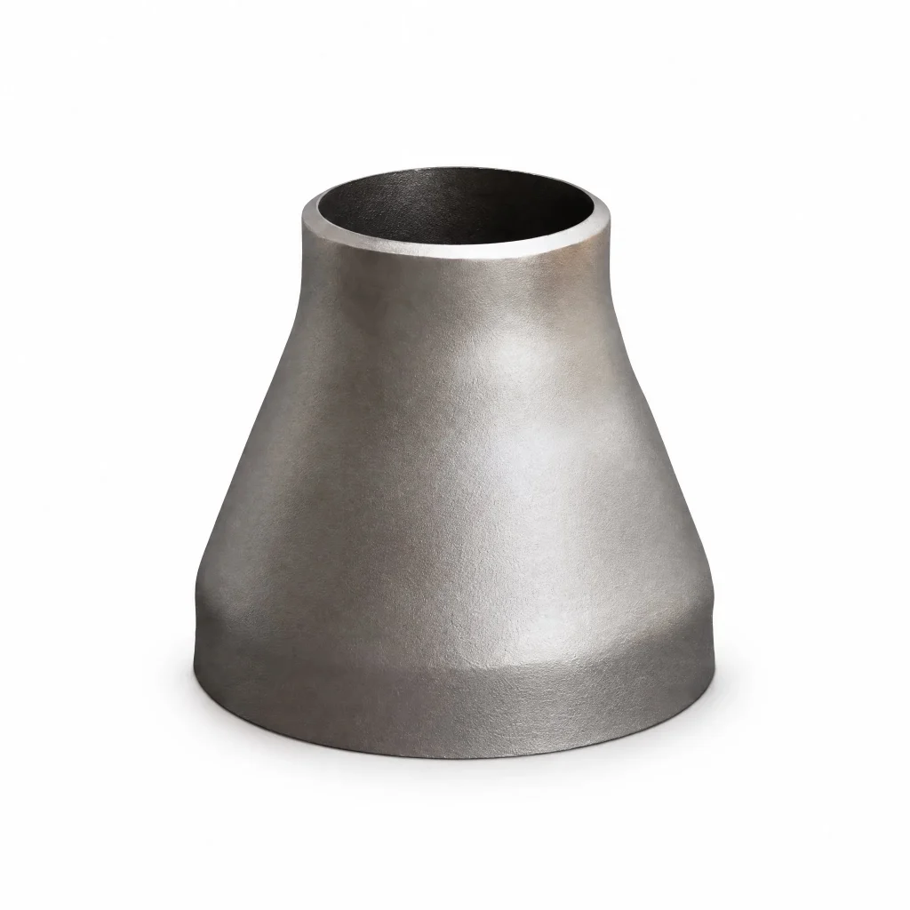
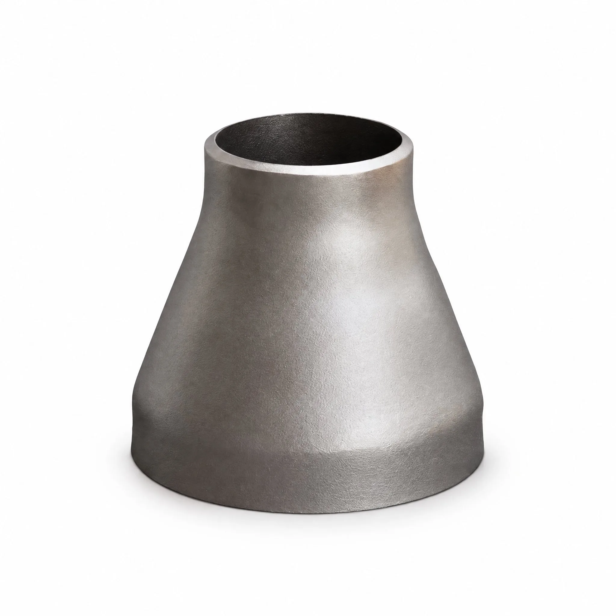
Concentric Reducer
Product Description
Reduces pipe diameter with the centerline maintained, ideal for vertical lines and gas services where a straight flow path is required.
Manufactured by cold forming or hot forging, followed by heat treatment where required, per ASME B16.9 dimensional tolerances. Available in Schedule 10 through XXS wall thicknesses.
Applications
Concentric reducers transition between pipe diameters while keeping the centerline perfectly aligned. They are the standard choice for vertical piping runs, gas and vapor service lines, and process piping where horizontal offset would cause liquid accumulation. Applications span oil and gas production, petrochemical plants, power generation, and industrial gas distribution systems.
Typical installations include vertical pump column transitions, compressor suction and discharge sizing, tower nozzle connections on distillation columns, and gas processing plant header reductions. In steam service, concentric reducers on vertical runs prevent condensate pooling that could cause water hammer in lines operating up to 425°C with WPB carbon steel.
Stainless concentric reducers serve pharmaceutical purified water loops, food and beverage product lines, and high-purity gas distribution. They are also used in boiler feedwater pump suction on vertical runs, cryogenic LNG transfer lines, and geothermal injection wells where centered flow is essential.
Quality Assurance & Certification
Concentric reducers are manufactured by hot extrusion or spinning to ASME B16.9 dimensional tolerances, with a smooth tapered transition and uniform wall thickness. The taper angle and end-to-end length follow standard dimensions. EN 10204 3.1 mill test certificates document heat chemistry and mechanical properties, with heat number marking for traceability.
NDT options include ultrasonic thickness measurement along the taper, radiographic inspection on welded reducers, and liquid penetrant testing on stainless grades. Third-party inspection by SGS, BV, or TUV can be arranged for power and oil and gas project hold points.
Butt-weld bevels are protected with plastic end caps. Carbon steel reducers receive anti-rust oil; stainless units are wrapped in protective film. Export packaging uses wooden crates and pallets, with labels showing size reduction (e.g., 6×4), schedule, material grade, heat number, and ASME B16.9 reference.
ASME Standard Data
This fitting is manufactured to ASME B16.9-2018, Factory-Made Wrought Buttwelding Fittings. This Standard covers overall dimensions, tolerances, ratings, testing, and markings for factory-made wrought buttwelding fittings in sizes NPS 1/2 through NPS 48 (DN 15 through DN 1200).
1. Scope and Size Range
This Standard covers overall dimensions, tolerances, ratings, testing, and markings for factory-made wrought buttwelding fittings in sizes NPS 1/2 through NPS 48 (DN 15 through DN 1200).
2. Units Policy — SI and U.S. Customary Must Not Be Mixed
This Standard states values in both SI (Metric) and U.S. Customary units. These systems of units are to be regarded separately as standard. Within the text and tables, the U.S. Customary units are shown in parentheses. The values stated in each system are not exact equivalents; therefore, it is required that each system of units be used independently of the other. Combining values from the two systems constitutes nonconformance with the Standard.
3. NPS–DN Relationship
DN/NPS: 15=1/2, 20=3/4, 25=1, 32=1-1/4, 40=1-1/2, 50=2, 65=2-1/2, 80=3, 100=4. NOTE: For NPS > 4, DN = 25 × NPS.
4. Materials — ASME B16.9 Table 5-1 Material Groupings
Wrought fittings covered by this Standard shall be in accordance with ASTM A234, A403, A420, A815, B361, B363, B366, or the corresponding specification in ASME BPVC Section II. The term “wrought” denotes fittings made of pipe, tubing, plate, or forgings.
| Group No. | Material | ASTM / ASME Specification |
|---|---|---|
| Group 1 | Carbon and low-alloy steels | ASTM A234/A234M, ASTM A420/A420M |
| Group 2 | Austenitic and duplex stainless steels | ASTM A403/A403M, ASTM A815/A815M |
| Group 3 | Nickel alloys | ASTM B366/B366M |
| Group 4 | Aluminum alloys | ASTM B361 |
| Group 5 | Titanium alloys | ASTM B363 |
Source: ASME B16.9-2018, Table 5-1 Material Groupings (corpus lines 674-676; OCR-recovered mapping, verified against standard group order).
5. Marking and WP / Special-Fitting Certification
Each fitting shall be permanently marked to show: (a) manufacturer’s name or trademark; (b) material identification, either the ASTM or ASME grade designation; (c) schedule number or nominal wall thickness in mm; (d) size — the NPS identification number related to the end connections; (e) compliance — see para. 4.4. A manufacturer may supplement these mandatory markings with others, including a DN size designation, but confusion shall be avoided.
Standard fittings: certified by prefix “WP”. Special fittings: certified by supplementary suffix: “S58” of ASTM A960 applies for A234, A403, A420; “S8” for A815; “SPLD” for B361, B363, B366.
6. Dimensional Tables — Concentric Reducers (ASME B16.9-2024 Table 6.1-11)
End-to-end H for concentric reducers, from NPS 3/4×1/2 up to 34×26.
| Nominal Pipe Size (Large × Small) | Large End OD | Small End OD | End-to-End H |
|---|---|---|---|
| 3/4 × 1/2 | 26.70 mm (1.05 in.) | 21.30 mm (0.84 in.) | 38 mm (1.50 in.) |
| 3/2 × 3/4 | 26.70 mm (1.05 in.) | 17.30 mm (0.68 in.) | 38 mm (1.50 in.) |
| 1 × 3/8 | 33.40 mm (1.32 in.) | 26.70 mm (1.05 in.) | 51 mm (2 in.) |
| 1 × 1/4 | 33.40 mm (1.32 in.) | 21.30 mm (0.84 in.) | 51 mm (2 in.) |
| 5 × 3 | 141.30 mm (5.56 in.) | 88.90 mm (3.50 in.) | 127 mm (5 in.) |
| 1-1/2 × 1 | 42.20 mm (1.66 in.) | 33.40 mm (1.32 in.) | 51 mm (2 in.) |
| 1-1/2 × 3/4 | 42.20 mm (1.66 in.) | 26.70 mm (1.05 in.) | 51 mm (2 in.) |
| 1-1/2 × 1/4 | 42.20 mm (1.66 in.) | 21.30 mm (0.84 in.) | 51 mm (2 in.) |
| 6 × 5 | 168.30 mm (6.62 in.) | 141.30 mm (5.56 in.) | 140 mm (5.50 in.) |
| 1-1/4 × 1-1/4 | 48.30 mm (1.90 in.) | 42.20 mm (1.66 in.) | 64 mm (2.50 in.) |
| 1-1/2 × 1 | 48.30 mm (1.90 in.) | 33.40 mm (1.32 in.) | 64 mm (2.50 in.) |
| 1-1/2 × 3/4 | 48.30 mm (1.90 in.) | 26.70 mm (1.05 in.) | 64 mm (2.50 in.) |
| 1-1/2 × 1/2 | 48.30 mm (1.90 in.) | 21.30 mm (0.84 in.) | 64 mm (2.50 in.) |
| 2 × 1-1/2 | 60.30 mm (2.38 in.) | 48.30 mm (1.90 in.) | 76 mm (3 in.) |
| 2 × 1-1/4 | 60.30 mm (2.38 in.) | 42.20 mm (1.66 in.) | 76 mm (3 in.) |
| 2 × 1 | 60.30 mm (2.38 in.) | 33.40 mm (1.32 in.) | 76 mm (3 in.) |
| 2 × 3/2 | 60.30 mm (2.38 in.) | 26.70 mm (1.05 in.) | 76 mm (3 in.) |
| 2-1/2 × 2 | 73 mm (2.88 in.) | 60.30 mm (2.38 in.) | 89 mm (3.50 in.) |
| 2-1/2 × 1-1/2 | 73 mm (2.88 in.) | 48.30 mm (1.90 in.) | 89 mm (3.50 in.) |
| 2-1/4 × 1-1/4 | 73 mm (2.88 in.) | 42.20 mm (1.66 in.) | 89 mm (3.50 in.) |
| 2-1/2 × 1 | 73 mm (2.88 in.) | 33.40 mm (1.32 in.) | 89 mm (3.50 in.) |
| 3 × 2-1/2 | 88.90 mm (3.50 in.) | 73 mm (2.88 in.) | 89 mm (3.50 in.) |
| 3 × 2 | 88.90 mm (3.50 in.) | 60.30 mm (2.38 in.) | 89 mm (3.50 in.) |
| 3 × 1-1/2 | 88.90 mm (3.50 in.) | 48.30 mm (1.90 in.) | 89 mm (3.50 in.) |
| 3 × 1-1/2 | 88.90 mm (3.50 in.) | 42.20 mm (1.66 in.) | 89 mm (3.50 in.) |
| 3-1/2 × 3 | 101.60 mm (4 in.) | 88.90 mm (3.50 in.) | 102 mm (4 in.) |
| 3-1/4 × 2-1/2 | 101.60 mm (4 in.) | 73 mm (2.88 in.) | 102 mm (4 in.) |
| 3-1/2 × 2 | 101.60 mm (4 in.) | 60.30 mm (2.38 in.) | 102 mm (4 in.) |
| 3-1/2 × 1-1/4 | 101.60 mm (4 in.) | 48.30 mm (1.90 in.) | 102 mm (4 in.) |
| 3-1/2 × 1-1/2 | 101.60 mm (4 in.) | 42.20 mm (1.66 in.) | 102 mm (4 in.) |
| 16 × 14 | 406.40 mm (16 in.) | 355.60 mm (14 in.) | 356 mm (14 in.) |
| 4 × 3-1/2 | 114.30 mm (4.50 in.) | 101.60 mm (4 in.) | 102 mm (4 in.) |
| 4 × 3 | 114.30 mm (4.50 in.) | 88.90 mm (3.50 in.) | 102 mm (4 in.) |
| 4 × 2-1/2 | 114.30 mm (4.50 in.) | 73 mm (2.88 in.) | 102 mm (4 in.) |
| 4 × 2 | 114.30 mm (4.50 in.) | 60.30 mm (2.38 in.) | 102 mm (4 in.) |
| 18 × 16 | 457 mm (18 in.) | 406.40 mm (16 in.) | 381 mm (15 in.) |
| 18 × 14 | 457 mm (18 in.) | 355.60 mm (14 in.) | 381 mm (15 in.) |
| 18 × 12 | 457 mm (18 in.) | 323.80 mm (12.75 in.) | 381 mm (15 in.) |
| 18 × 10 | 457 mm (18 in.) | 273 mm (10.75 in.) | 381 mm (15 in.) |
| 36 × 30 | 914 mm (36 in.) | 762 mm (30 in.) | 610 mm (24 in.) |
| 20 × 18 | 508 mm (20 in.) | 457 mm (18 in.) | 508 mm (20 in.) |
| 20 × 16 | 508 mm (20 in.) | 406.40 mm (16 in.) | 508 mm (20 in.) |
| 20 × 14 | 508 mm (20 in.) | 355.60 mm (14 in.) | 508 mm (20 in.) |
| 20 × 12 | 508 mm (20 in.) | 323.80 mm (12.75 in.) | 508 mm (20 in.) |
| 38 × 34 | 965 mm (38 in.) | 864 mm (34 in.) | 610 mm (24 in.) |
| 22 × 20 | 559 mm (22 in.) | 508 mm (20 in.) | 508 mm (20 in.) |
| 22 × 18 | 559 mm (22 in.) | 457 mm (18 in.) | 508 mm (20 in.) |
| 22 × 16 | 559 mm (22 in.) | 406.40 mm (16 in.) | 508 mm (20 in.) |
| 22 × 14 | 559 mm (22 in.) | 355.40 mm (14 in.) | 508 mm (20 in.) |
| 24 × 22 | 610 mm (24 in.) | 559 mm (22 in.) | 508 mm (20 in.) |
| 24 × 20 | 610 mm (24 in.) | 508 mm (20 in.) | 508 mm (20 in.) |
| 24 × 18 | 610 mm (24 in.) | 457 mm (18 in.) | 508 mm (20 in.) |
| 24 × 16 | 610 mm (24 in.) | 406.40 mm (16 in.) | 508 mm (20 in.) |
| 40 × 30 | 1016 mm (40 in.) | 762 mm (30 in.) | 610 mm (24 in.) |
| 26 × 24 | 660 mm (26 in.) | 610 mm (24 in.) | 610 mm (24 in.) |
| 26 × 22 | 660 mm (26 in.) | 559 mm (22 in.) | 610 mm (24 in.) |
| 26 × 20 | 660 mm (26 in.) | 508 mm (20 in.) | 610 mm (24 in.) |
| 26 × 18 | 660 mm (26 in.) | 457 mm (18 in.) | 610 mm (24 in.) |
| 42 × 34 | 1067 mm (42 in.) | 864 mm (34 in.) | 610 mm (24 in.) |
| 28 × 26 | 711 mm (28 in.) | 660 mm (26 in.) | 610 mm (24 in.) |
| 28 × 24 | 711 mm (28 in.) | 610 mm (24 in.) | 610 mm (24 in.) |
| 28 × 20 | 711 mm (28 in.) | 508 mm (20 in.) | 610 mm (24 in.) |
| 28 × 18 | 711 mm (28 in.) | 457 mm (18 in.) | 610 mm (24 in.) |
| 44 × 40 | 1118 mm (44 in.) | 1016 mm (40 in.) | 610 mm (24 in.) |
| 30 × 28 | 762 mm (30 in.) | 711 mm (28 in.) | 610 mm (24 in.) |
| 30 × 26 | 762 mm (30 in.) | 660 mm (26 in.) | 610 mm (24 in.) |
| 30 × 24 | 762 mm (30 in.) | 610 mm (24 in.) | 610 mm (24 in.) |
| 30 × 20 | 762 mm (30 in.) | 508 mm (20 in.) | 610 mm (24 in.) |
| 46 × 42 | 1168 mm (46 in.) | 1067 mm (42 in.) | 711 mm (28 in.) |
| 32 × 30 | 813 mm (32 in.) | 762 mm (30 in.) | 610 mm (24 in.) |
| 32 × 28 | 813 mm (32 in.) | 711 mm (28 in.) | 610 mm (24 in.) |
| 32 × 26 | 813 mm (32 in.) | 660 mm (26 in.) | 610 mm (24 in.) |
| 32 × 24 | 813 mm (32 in.) | 610 mm (24 in.) | 610 mm (24 in.) |
| 48 × 44 | 1219 mm (48 in.) | 1118 mm (44 in.) | 711 mm (28 in.) |
| 34 × 32 | 864 mm (34 in.) | 813 mm (32 in.) | 610 mm (24 in.) |
| 34 × 30 | 864 mm (34 in.) | 762 mm (30 in.) | 610 mm (24 in.) |
| 34 × 26 | 864 mm (34 in.) | 660 mm (26 in.) | 610 mm (24 in.) |
Source: ASME B16.9-2024 Table 6.1-11, pp. 34–35. Large and small end outside diameters at bevel shown in mm (in.).
8. Proof Test Coverage — ASME B16.9 Table 9.2.1-1
| Fitting Tested (Proof Test) | Configurations Qualified by This Test |
|---|---|
| 同心异径管 (Concentric reducer) | 相同或较小内过渡角的同心异径管 |
(3) 直锥型(无切线)与钟形异径管视为不同构型,需单独试验。
(4) “过渡角”定义为圆锥段的角度:同心异径管 = arctan(直径差 / 2×长度);偏心异径管 = arctan(直径差 / 长度)。
Proof Test Factor f — ASME B16.9 Table 9.3.1-1
| Number of Proof Tests on Same Configuration | Test Factor f |
|---|---|
| 1 | 1.1 |
| 2 | 1.05 |
| Three or more | 1.0 |
P = 2 S f t / D. D = specified outside diameter of pipe; f = test factor from Table 9.3.1-1; S = actual tensile strength of test fitting; t = nominal pipe wall thickness of the pipe the fitting marking identifies.
The fitting shall withstand the minimum calculated pressure for at least 180 s (3 min).
The test shall be conducted with water. Trapped air in the assembly shall be purged prior to the start of the test.
Critical areas are normally the inner radius of elbows, the crotch of tees and crosses, the knuckle radius of caps, and the large ends of reducers.
Source: ASME B16.9-2018. Hydrostatic testing of wrought fittings is not required by this Standard. All fittings shall be capable of withstanding, without leakage or impairment of serviceability, a hydrostatic test pressure required by the applicable piping code for seamless pipe of material equivalent to, and of the size and wall thickness the fitting marking identifies.
Request a Quote for This Product
Tell us your standard, size, material and quantity — our team will reply within 24 hours.
Frequently Asked Questions
Carbon steel A234 WPB, stainless A403 WP304/304L/316/316L, low-temperature A420 WPL6, and alloy steel A234 WP11/WP22 on request.
NPS 1/2″ to 48″, all standard schedules from SCH 10 to XXS. Custom sizes per drawing available with 15–30 day lead time.
Yes — EN 10204 3.1 MTC, material traceability, and third-party inspection (BV / SGS / TUV) upon request.