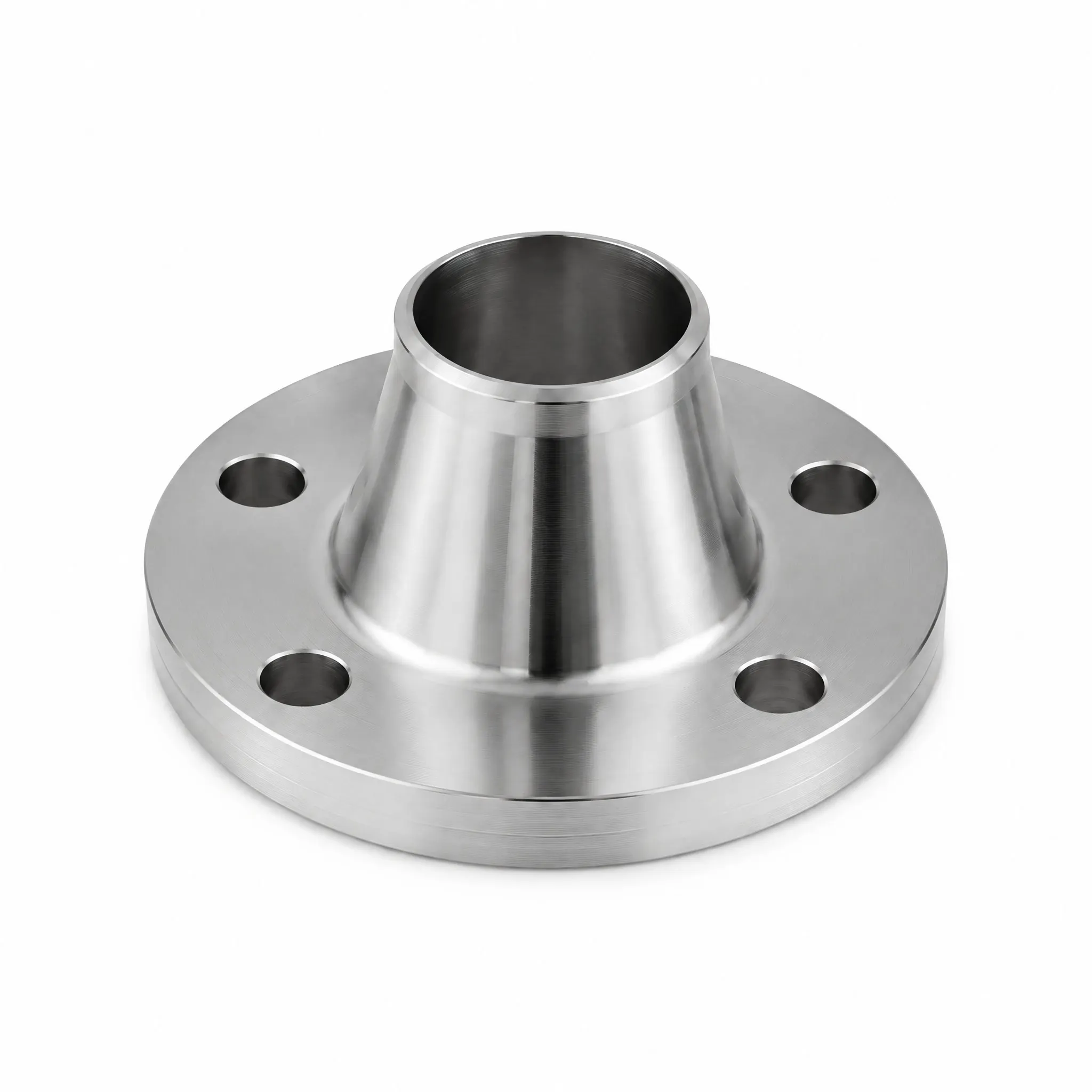
Weld Neck Flange
Product Description
The Weld Neck Flange is the most widely used flange type in high-pressure and high-temperature services. Its long tapered hub provides a smooth transition from pipe wall thickness to flange thickness, significantly reducing stress concentration at the joint and improving fatigue resistance under cyclic loading.
Butt-welded to the pipe, this flange offers a full-penetration weld joint that is radiographically inspectable — the preferred connection for critical applications such as oil & gas pipelines, refinery process lines, chemical plants, and power generation systems.
Every flange is supplied with a mill test certificate (EN 10204 3.1), material traceability, and optional third-party inspection (BV / SGS / TUV).
Applications
Weld neck flanges are the preferred connection for critical high-pressure, high-temperature piping in oil and gas upstream and downstream facilities. They are widely specified for refinery process units operating at pressures up to Class 2500 (425 bar rating at ambient) and temperatures from -29°C to 425°C with carbon steel A105, or up to 538°C with austenitic stainless F304/F316.
Typical applications include pipeline transmission stations, gas processing plants, petrochemical reactors, power boiler headers, and offshore platform piping systems handling crude oil, natural gas, steam, and hydrocarbon media. The butt-weld joint allows radiographic inspection, making weld neck flanges mandatory for cyclic loading and fatigue-sensitive services per ASME B31.3 and B31.4 codes.
They are also found in LNG regasification terminals, hydrogen service piping, and chemical injection skids where leak-tight integrity over decades of operation is non-negotiable. The tapered hub distributes stress smoothly, reducing vibration-induced failure in pump and compressor discharge lines.
Quality Assurance & Certification
Every weld neck flange is manufactured under our ISO 9001-certified quality management system and supplied with an EN 10204 3.1 mill test certificate covering chemical composition, mechanical properties (tensile yield, impact), and dimensional inspection per ASME B16.5-2025 tolerances. Each flange carries a unique heat number etched on the outer diameter for full material traceability from mill to installation.
Non-destructive testing options include Radiographic Testing (RT) of the weld preparation, Ultrasonic Testing (UT) for lamination checks, Magnetic Particle Testing (MT) for surface cracks on carbon steel, and Dye Penetrant Testing (PT) on stainless grades. Third-party inspection by BV, SGS, or TUV can be arranged at the mill or before shipment.
All flanges are coated with anti-rust oil, protected by plastic end caps, and packed in export-worthy wooden crates or pallets suitable for sea freight. Facing surfaces are protected with plastic guards. Each bundle is labeled with product identification, heat number, and net weight for customs and warehouse handling.
Technical Specifications (ASME B16.5)
ASME Standard Data
Dimensional, pressure–temperature and material data transcribed from the ASME B16.5-2025 standard (NPS 1/2–24, Metric/Inch). Ratings shown for carbon steel Group 1.1 (ASTM A105) and stainless Groups 2.1–2.3 (A182 F304/F316 family).
1. Pressure–Temperature Ratings — Group 1.1 Materials (A105) — SI Units (bar)
Source: ASME B16.5-2025, Table 2-1.1 (SI Units). Notes: (1) Prolonged use above 427°C permissible but not recommended; (2) only killed steel above 455°C; (3) not over 260°C; (4) not over 371°C; (5) not over 343°C; (6) see para. 2.5.3 for minimum temperatures.
2. Pressure–Temperature Ratings — Group 1.1 Materials (A105) — U.S. Customary Units (psig)
Source: ASME B16.5-2025, Table 2-1.1C (U.S. Customary Units). SI and US tables are independently rounded per ASME practice.
3. Material Group Correspondence (ASME B16.5, Table 1.1-1)
Source: ASME B16.5-2025, Table 1.1-1 (Material Groups). “…” denotes not applicable in the standard.
4. Minimum Use Temperatures (ASME B16.5, Appendix G, Table G-1)
Source: ASME B16.5-2025, Nonmandatory Appendix G, Table G-1 (Example Minimum Use Temperatures). Impact testing requirements per applicable code.
5. Weld Neck Flange Dimensions — Class 150, SI Units (mm, ASME B16.5 Table 9)
Source: ASME B16.5-2025, Table 9 (Class 150, SI). Class 300/400/600/900/1500/2500 dimensions also per Table 9. Full column set (incl. hub X and A_h) per standard.
4. Dimensional Table — Class 150 Weld Neck Flanges (SI, mm)
Key dimensions for Class 150 welding neck flanges, NPS 1/2–24, transcribed from ASME B16.5-2025 Table 9. O = flange outside diameter; t_f = minimum flange thickness; X = hub diameter; A_h = hub diameter at start of chamfer; Y = length through hub (welding neck); B = minimum bore. All values in mm.
Source: ASME B16.5-2025 Table 9, Class 150, SI Units. B column for NPS 14 and larger marked (9) — dimension to be specified by the purchaser (per ASME B16.5-2025 Table 9).
Flange Dimensions — ASME B16.5-2025 Table 9 (SI Units, mm)
Complete flange dimensional data extracted from ASME B16.5-2025 (Pipe Flanges and Flanged Fittings), Table 9, for all pressure classes 150–2500. All values in millimeters (SI). Data verified against the ASME B16.5-2025 source corpus; the standard’s footnote numbering is preserved exactly.
Class 150 Flanges — ASME B16.5-2025 Table 9 (SI Units, mm)
Flange dimensions, NPS 1/2–24, 21 rows. Values in millimeters (SI).
Class 300 Flanges — ASME B16.5-2025 Table 9 (SI Units, mm)
Flange dimensions, NPS 1/2–24, 21 rows. Values in millimeters (SI).
Class 400 Flanges — ASME B16.5-2025 Table 9 (SI Units, mm)
Flange dimensions, NPS 1/2–24, 21 rows. Values in millimeters (SI). Rows marked * use the dimensions of Class 600 per Note (5).
Class 600 Flanges — ASME B16.5-2025 Table 9 (SI Units, mm)
Flange dimensions, NPS 1/2–24, 21 rows. Values in millimeters (SI).
Class 900 Flanges — ASME B16.5-2025 Table 9 (SI Units, mm)
Flange dimensions, NPS 1/2–24, 19 rows. Values in millimeters (SI). Rows marked * use the dimensions of Class 1500 per Note (5).
Class 1500 Flanges — ASME B16.5-2025 Table 9 (SI Units, mm)
Flange dimensions, NPS 1/2–24, 19 rows. Values in millimeters (SI).
Class 2500 Flanges — ASME B16.5-2025 Table 9 (SI Units, mm)
Flange dimensions, NPS 1/2–24, 20 rows. Values in millimeters (SI). NPS 14–24 are not included in the extracted corpus — see ASME B16.5-2025 Table 22.
Notes — ASME B16.5-2025 Table 9
- Note (5) — Class 400: Use Class 600 dimensions in this size. Values in rows marked * are taken from Class 600.
- Note (5) — Class 900: Use Class 1500 dimensions in this size. Values in rows marked * are taken from Class 1500.
- Note (6) — Class 900 / Note (8) — Class 300 / Note (9) — Class 150 (B column, NPS 14 and larger): To be specified by the purchaser.
- Note (5) — Class 600, 1500, 2500 (B column): To be specified by the purchaser.
- Classes 900, 1500 and 2500 do not list NPS 3 1/2 and NPS 22 in ASME B16.5-2025 Table 9.
- Class 2500 Table 9 covers NPS 1/2–12 in this dataset; NPS 14–24 refer to ASME B16.5-2025 Table 22.
- “—” = value not fully rendered in the extraction corpus (PDF text-layer conversion); refer to the standard original. Where a footnote text was truncated during extraction, the standard’s note numbering is preserved as-is.
- Blind (blank) flanges: hub and bore columns (X, Ah, Y, T, B2/B1/B, r, Q, D) do not apply; the O and tf columns remain valid.
- Socket-welding flanges cover NPS 1/2–4 per ASME B16.5-2025; rows above NPS 4 apply to the other flange types (WN / Threaded / SO / Lapped / Blind).
Stainless Steel (Group 2.1) Pressure–Temperature Ratings — ASME B16.5-2025
Pressure–Temperature Ratings, Group 2.1 Materials (18Cr-8Ni / 18Cr-8Ni-Mo) — ASME B16.5-2025 Table 2-2.1 (SI Units, bar)
Material designations in Group 2.1 — austenitic stainless steels (F304, F304H, F316 and related forgings, castings and plates). Working pressures in bar by class; values for temperatures in °C.
Notes — ASME B16.5-2025 Table 2-2.1 (Group 2.1)
- Group 2.1 covers 18Cr-8Ni (e.g. A182 F304, A351 CF3/CF8, A240 304) and 18Cr-8Ni-Mo (e.g. A182 F316, A351 CF3M/CF8M, A240 316) austenitic stainless steels.
- Working pressures shown in bar (SI units). Class 150 rating at room temperature is 19.1 bar, Class 2500 is 414.3 bar, per Table 2-2.1.
- The Group 1.1 (carbon steel A105 / WCB) ratings are provided in the earlier section of this page.
- “—” = value not fully rendered in the extraction corpus; refer to the standard original.
- Data extracted and verified against the ASME B16.5-2025 source corpus; footnote numbering preserved as-is.
Request a Quote for This Product
Tell us your standard, size, material and quantity — our team will reply within 24 hours.
Frequently Asked Questions
The Weld Neck flange has a tapered hub that is butt-welded to the pipe, providing full penetration and superior stress distribution. Slip-On flanges slide over the pipe and are welded both inside and outside — easier to align but with lower fatigue strength, making Weld Neck the preferred choice for severe service.
Ratings follow ASME B16.5 §2 Pressure-Temperature Tables. For ASTM A105 (Group 1.1): Class 150 rated 20 bar at 38°C, Class 300 rated 50 bar at 38°C, Class 600 rated 102 bar at 38°C. Ratings derate as temperature increases.
Yes, every flange ships with an EN 10204 3.1 mill test certificate and full material traceability. Third-party inspection by BV, SGS, or TUV can be arranged upon request.
MOQ is 1 piece for standard sizes. Stock items ship in 7–15 days; custom specifications (special materials, sizes, or facings) ship in 15–30 days.